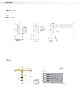
L68B3 Mast Section The hydraulic system of the tower crane and the whole process of the hydraulic jack-up connection
the tower crane as an important lifting equipment, tons of goods are moved for construction and transportation. How does the tower crane carry these heavy objects to high places? It depends on the hydraulic lifting parts of the tower crane. The tower crane is divided into several parts as follows: (1) metal components, such as lifting arm, tower body, turntable, bearing base, balance arm, base frame, spire, etc.
L68B3 mast section is the best in this field

Working Mechanism, such as lifting mechanism, luffing mechanism, trolley traction mechanism, slewing mechanism and traveling crane of cart, safety device, etc. For example, limit switch, overload safety device, buffer stop device, wire rope anti-release device, anemometer, emergency safety switch, safety protection sound signal machine, etc. . The main components of tower crane hydraulic system are hydraulic pump, hydraulic cylinder, control element, tubing and pipe joint, oil tank and hydraulic oil filter. Tower Crane hydraulic pump and hydraulic motor is the most complex part of the hydraulic system, hydraulic pump oil into and through the pipeline to the hydraulic cylinder or hydraulic motor, and hydraulic cylinder is the executive component of the hydraulic system. Hydraulic pump can be seen as the hydraulic and heart, is the hydraulic energy source. The hydraulic pump used in the hydraulic lifting system of tower crane in China is mostly CB-G gear pump, the symbol of CB non-gear, the axial clearance of Hegelong g is fixed, the working pressure is 12. 5 ~ 16 MPA. A hydraulic jack-up the whole process can be divided into 7 steps, respectively: 1. The balance weight is moved so that the tower body is not subjected to unbalanced Torque, the crane arm is in position, oriented in the same direction as the imported track and locked, and a standard section of the tower body is lifted and placed on the ferry trolley; 2. Jack Up; 3. The locating pin is in place and locked, the Piston Rod is lifted to form an introduction space in the bushing; 4. Introduction of Standards Section; 5. Bring up the standard section, roll out the ferry trolley;. Get The standard section in place and install the connecting bolts. Slightly upward lifting, pull out the positioning lock so that the transition section and the tower crane has been connected into one body.
L68B3 mast section is the best in this field